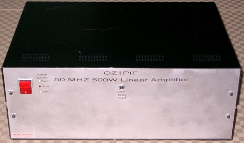
50MHz 500W IRF510 based Amplifier
This amplifier project was based on a prototype circuit developed for the HF-bands by OZ3SW, Steen Møller. The HF project was eventually scrapped because of widely varying gain from 160m to 10m.
 PCB now available from Far Circuits (see below)
It looked sufficiently interesting, for me to mature the basic circuit design into a singleband 50MHz amplifier.
The basic building block is a 4+4 push-pull configuration, biased at
500mA, delivering 250W out for 10W in at 40V/10A. To make life easy on
yourself, use devices from a single batch, as these are most likely to be closely
matched. I've used devices from Intersil (Fairchild). These are no longer
being produced, but there should be an ample supply in the distribution
channels. The FQP7N10 device looks to be a very suitable (and somewhat
better) alternative, but I have not been able to make them work as a direct
substitution, I suspect that they have a somewhat higher gain figure, and
would need a lower S/D V to work properly. Frankly I don't have the patience
or incentive to experiment further along this line, as my present amplifier
works very well and exhibit no problems whatsoever, I even have a small
supply of spare IRF510 from the original batch - should something untoward
happen!
The Vishay IRF510PBF is as the original ones used, with a Drain
dissipation of 43Watts, but have not been tested by me.
The individual IRF510s are mounted on the heatsink using Aluminium Oxide
heat-transfer isolation bricks and silicone grease, for sufficiently
low coupling between the MOSFETs and the heatsink to insure stability.
The type of Aluminium oxide wafers used to transfer the heat
without introducing a large capacitor is a Fischer Elektronik GmbH (Germany) type
AOS220.
I bought them at Arrow Electronics Nordic at .20£ a piece for
100 pieces a couple of years ago.
The input transformer (9:1) uses 4C65 cores, and the output transformer (1:4) uses thin air!
L4 is just a choke, and thus
fairly uncritical, a couple of turns of the supply wire on any
available piece of ferrite, see the photos, it's just below the
eletrolytic cap. on the module photo.
![]()
T1 is made by threading a piece of wire three times (the primary)
through a piece of coax outer conductor (the secondary) around four
4C65(*See note below on core material) cores glued together using
Cyanoacrylate (Superglue), thus creating a 9:1 impedance transformation
and a very reasonable input match. See also fig. 4 & 5 in AN749
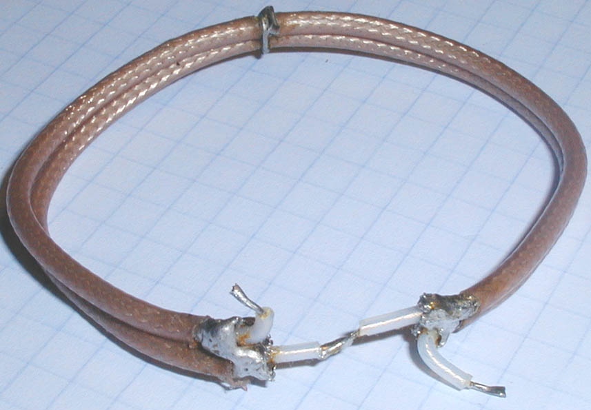
The output transformer is made
from two pieces of teflon coax (RG316) 14.5cm in length, the outer
conductors joined at the middle and the ends, for the primary, and the
inner conductors in series as two windings (the secondary) giving a 1:4
ratio and a close match to 50 Ohms (fine tune with C41), the B+ supply
must be as near the midpoint of the primary as possible!
*I've used 4 x Ferroxcube core Material TN14/9/5 (4C65); Part No: 4322 020 9718
an equivalent Amidon would be Material Type 61 Part No: FT50-61
A very thorough description of construction of HF-transformers can be found in : Motorola Application Note AN749
The combiner used, is a simple 1/4-lambda combiner made from 75Ohm Coax,
input splitter made the same way.
The end result is then passed through a low loss Elliptical LP filter with
a
70dB notch at 2nd harmonic and 80dB at 3rd.
Bias is 500mA pr module; IMD3 has not been measured, but reports on the band have been uniformly good.
More than 2000 QSOs have been made so far with this amp. Only
mishap was during an F2 opening to NA in 2001, when i forgot to reduce
tranceiver output to 20W, I still made 4 and a ½ QSOs before things
went avry (12 of 16 IRF510 blew loudly and smelly) These were quickly
replaced (at less than 30c a piece!) and no one ever commented on the
output, despite the vast overdrive.
This event taught me never to rely on manual throttling of drive to an
amplifier - things will go wrong, and Murphy taught us that it'll happen
when most inopportune, e.g. when in the middle of a humongous pile-up for
the rarest of DXs! This amplifier now has a power attenuator built-in, to
reduce the 100W from my FT-847 to the 20W required for full output. (As do
my other amplifiers - all of them!) An added benefit is the reduction of
splatter produced by the overshoot from the tranceivers output regulator,
the more you throttle back the worse it gets - some modern tranceivers
produce spikes of more than 150W on VHF - and the FT-847 is far from the
worst of the bunch!
You can, of cause, combine an arbitrary number of the 250W modules to
obtain your desired output level, my reason for deciding on 500W was the
availability of a suitable powersupply.
Schematic here (in PDF format)
PCB lay-out (click to obtain full resolution image), Size of PCB: 118mm x 85mm split along the horizontal line. Etched on double sided material. All drill holes for component mounting to be counter-sunk on the back-side, the rest are being used for "through plating" to connect the ground areas on both sides of the PCB.
Far Circuits (http://www.farcircuits.net/
) have now (Feb. 2012) manufactured a set of PCBs, complete
with eyelet inserts for connecting front and back, selling
for US 18$ for the set.
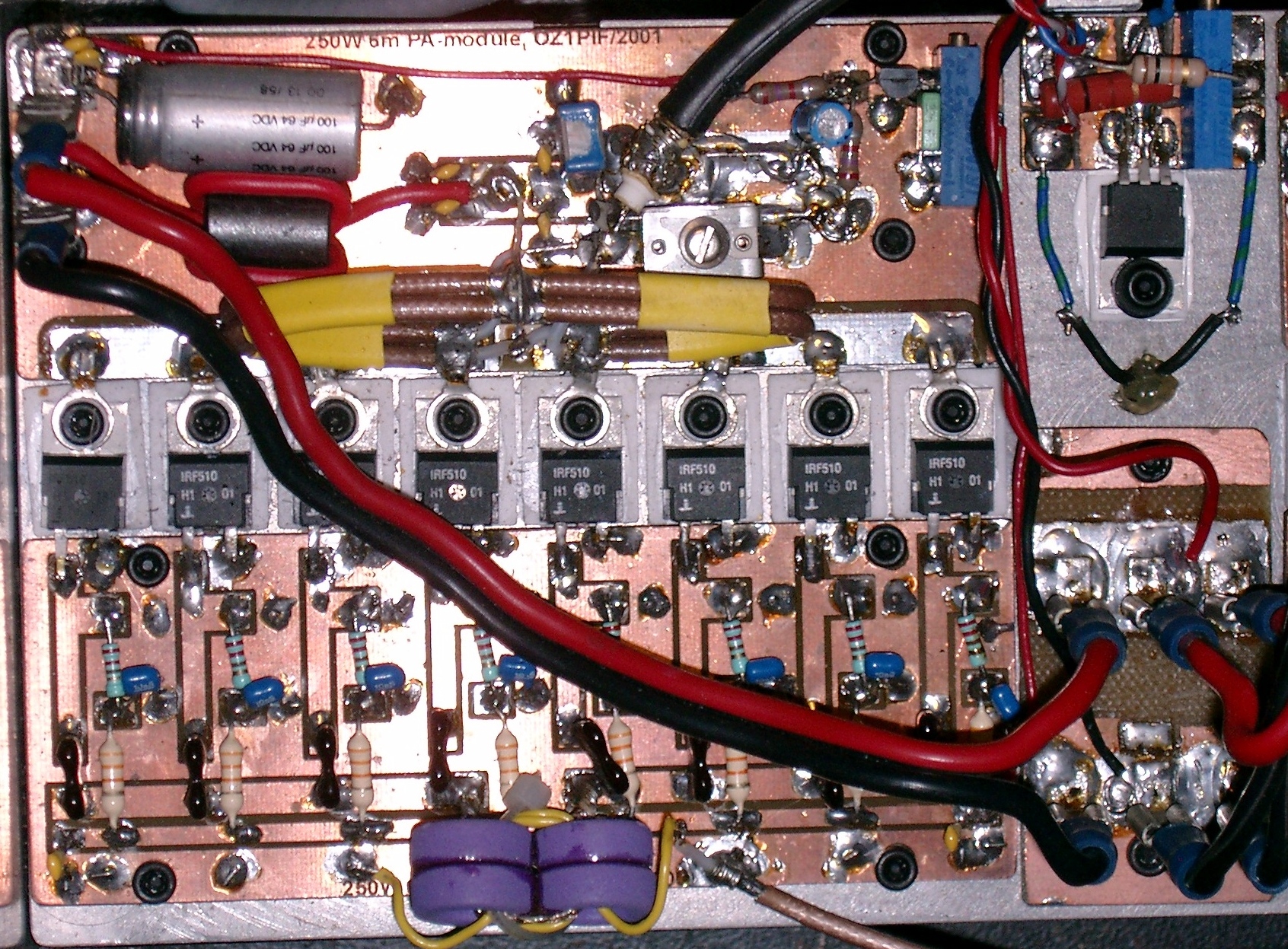
The finished module (since the PCB design, I have added the bias circuit in the upper right corner - dead bug fashion) Click to see hi-res version. The small circuit added to the heat-sink, next to the bias circuit, is a fan-speed controller (see elsewhere on my homepage)
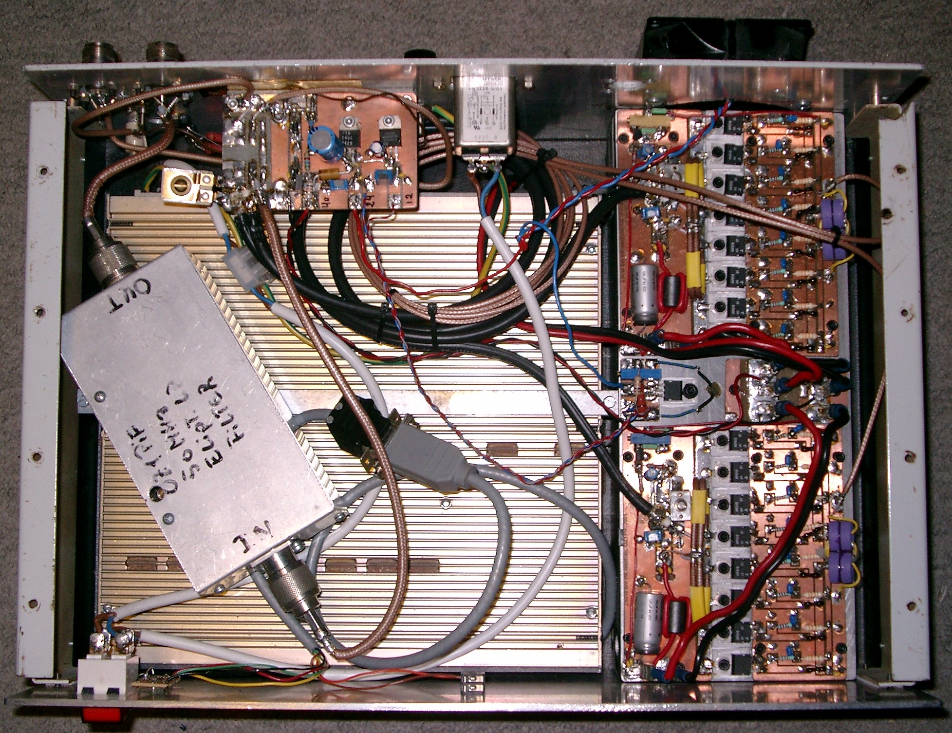
The completed amplifier (as usual, click to get hi-res version)
The large finned object is a surplus commercial 800W Switch Mode PS. On top of that the Elliptical LP filter. The small PCB over the PS, contains 12- and 24V regulators and changeover relays (not seen, but cheap open frame 20A Washing machine type, but still better than -20dB return loss at this frequency!) The grey RS-232 cable connects contol LEDs on the front to the PS.
The coils of coax cable are the splitters and combiners
Last, but not least, the whole thing - ready to plug in - weighs just under 12.5Kg (< 30 pounds, if you don't understand metric), ideal for /P use or DXpedition travel - and that's with the present heavy duty steel cabinet, I could probably shave off another 3-4 Kg with an Aluminium enclosure.
ADDENDUM July 2006:
I've had a small, but sometime very annoying, problem right from the start: In Rx mode I had a small but just audible broadband noise on a very quiet band, no problem when working a contest, ES-opening or F2, but bad enough to be a problem when working very weak signals in JT6M or JT65 modes. Just recently i was hunting a very rare Norwegian square, and had to turn off the amplifier during recieve periods in order to be able to decode him at all! That's when I decided to finally do something about it!
It quickly turned out to be RF-Hash coming from the SMPS and the Fan, but various attempts to get rid of it it proved fruitless, and, I realized that, instead of curing the decease, I had to do something about the symptoms. The noise entered my signal path at several points internally to the amplifier (demonstrated by taking the two coax-cables connected by a female-female adapter, routing this through the amp, with no detectable noise when the amp was turned on. The main culprits were determined to be the open frame RF-relays and coax joints done on the cheap at various points.
I thus decided to completely redo internal RF-cabling, using high quality coax relays, cable (RG400) and crimped N-connectors throughout. I also decided to redo the 25V and 12V power adaptation, and added a transistorized PTT- circuit while I was at it.
I'm happy to report that the rebuild has been a complete success, I can no longer measure or hear anything coming from the amp in Rx mode (at least below -100dBm).
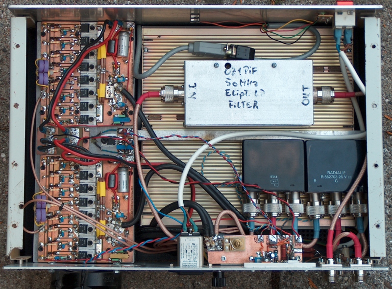
The modified internal layout!
Addendum Jan. 2010:
It seems that OH7LMQ / Timo has solved the oscillation problem with other/newer IRF510s. With Timo's permission I quote:
Hello
I contacted you about month ago, for the 50Mhz amplifier oscillating
issues. The reason of this message is to share information and
experiences, if some builder asks for help.
Looks like i have found a remedy for the parasitic oscillation problems,
which may occur with vishay brand irf510:s.
I did install 4r7 SMD resistors in series to gate lead, right to fet:s
gates, and that was right for the money ! Now the amp looks like it is
full stable at any bias voltage, what i have tested few hours.
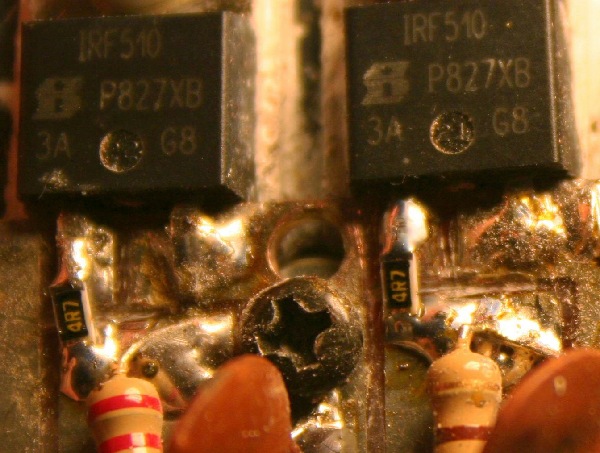
4r7 smd resistors i had on hand. I don't know the best value, however.
I have tested with 28 to 40 volts, no oscillations whatsoever, nor when
stopping to transmit and the bias left running.
One thing i noticed too, the input WSWR also improved from good to
exellent. It was abt. 1:1,6 before and now the reverse power is hardly
seen on swr meter.
in 5W drive and 70+ watts output, the gain was reduced some db
fractions. Maximum gain with these was well over 12 db before the
resistors, but unusable due the oscillations. Also with 5w input,
a 28 volt supply produced better efficiency.
Next i will test with 10w drive and 40 volts, when i get bigger power
supply and rig capable of 10 watts.
Best dx's
DE OH7LMQ / Timo
Addendum Oct. 2013
Ilkka, OH5IY has made some very interesting measurements:
8*IRF510 50 MHz amplifier with 4.7 ohmIlkka has also made some comments (slightly edited by me):
gate resistors:
drive Vdc Pout Idc eff.
5 W 28 V 65 W 5.75 A 40%
5 40 75 6.5 29
10 28 110 7.7 51
10 40 145 9.3 39
15 28 140 9.2 54
15 40 205 10.9 47
20 28 165 10.2 58
20 40 250 11.8 53
The FETs I used, were IRF510 Vishay Siliconix "Tian", Y33K AS
The Pout values were with LPF&coupler losses, about 0.35 dB.
Power monitoring coupler has 2 pickups for reflected power. The longer one is used to fold-back the bias for SWR protection, now tuned to cut in at SWR 1:2 reducing Pout to about 25-30 W, but it depends on the component values used. I have only tried it with 1m of RG-59 before dummy-load and it worked OK. I have no idea if it saves the FETs if there is no antenna connected. If driven under 50% power, FETs should not fail even without any SWR protection.
Noted that the PCB could do with a small fan, added one, ran it for 1 h 100 W output and now nothing was too hot to touch around the FETs or the output transformer.
I tested the amplifier with 10 mW output level at broader bandwidth and it seems it works from 20 MHz up, I suspect 70 MHz would be OK too (60 MHz was some dB off only), if the LPF was not built for 50 MHz, it might go even higher with reduced gain available of course. But I would not discard the idea of using it on 50 and 70 MHz (and maybe 28 if necessary).
Times seems to have pass by these FETs, Farnell sells a 300 W 40 V LDMOS that goes up to 225 MHz. Still 10 x more expensive but simpler and 1 W drive is enough.
TV band I pallet amplifiers are not overwhelmingly expensive either these days. They surely do 50 and 70 MHz. Such a pallet would be a direct substitute to this IRF510 amplifier without any modifications (except lower drive it needs), just bolt on, and wire up.
73 de Ilkka