Signalink USB Mods
Up until now I've been using home brew interfaces both for use in the shack and /p, but I needed to reduce the cable fest and to find a simpler solution (and to be quite honest, my first several attempt at home brewing an USB SoundCard and VOX solution have failed miserably).
I then happened to see a review of the Tigertronics "SignaLink USB" product in QST finding that this could be a plug-in solution to my setup.
First problem: unavailable! 4-6 weeks delivery quoted by the factory as well as dealers! When I finally found that a local dealer BM-Radio, had them in stock, I immediately ordered one, and got it two days later. Hurrah!
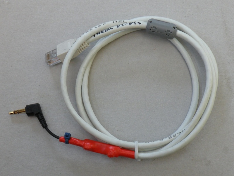
When I unpacked it I found a ready confectioned cable for connection to the 8-pin microphone plug on the FT-847 and a 3.5mm stereo jack cable for connection to the Phone jack (1/4" jack on the 847), quick connection to the radio followed by an equally quick boot of Ubuntu - which recognized the new SoundCard automatically! and start-up of WSJT7 in FSK441 mode immediately yielded a working set-up. Literally less than 5 minutes from package arrival to operating!
This is where the real story begins.
The first crucial (to my operating style at least) modification, was to fashion a cable to connect the SignaLink USB directly to the Data port on the FT-847. No problem, well documented on the manufacturer's support page! (I chose a different solution, I added the capacitor and resistor directly to the 3.5mm jack, so that I'm able to switch interface cables instantly (I now have interface cables ready for the front of the FT-847, the data port of the FT-847 and the ACC1 port of the ICOM IC-756ProIII, all interchangeable at the RJ-45 socket without having to open the box for rewiring)
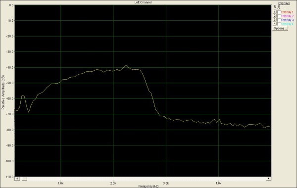
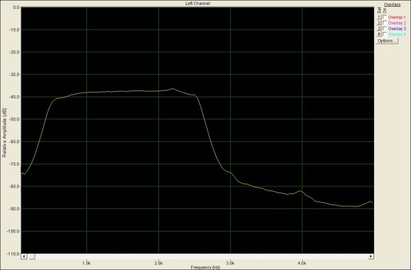
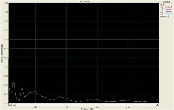
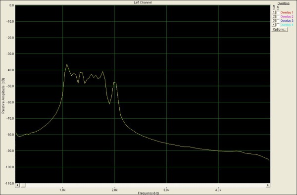
Running WSJT in FSK-441 mode, I immediately noticed this (upper right corner of the WSJT Window) "listening" to white noise on the 144MHz band:
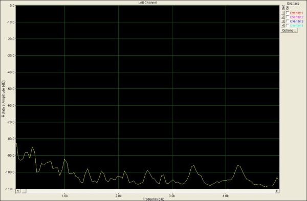
Where I'm used to this (Home brew interface to SB-16 Sound Card):
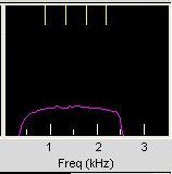
Notice the significant drop-off at the low end of the AF spectrum.
At this point I had to switch operating systems to WinXP in order to use an old copy of "SpectraLab" for a closer look at things.
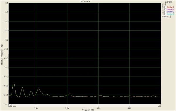
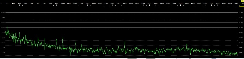
This is what the above looks like in SpectraLab (1V RMS = 0dB):
I then (accidentally) looked at the noise floor of the SignaLink USB (cable un-plugged):

(I have later found out that my Zepto Notebook has an USB port that is much noisier than normal!)
I checked with another USB Sound Card also on the Zepto:

Which is really significantly better!
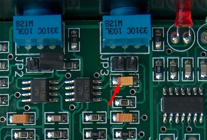
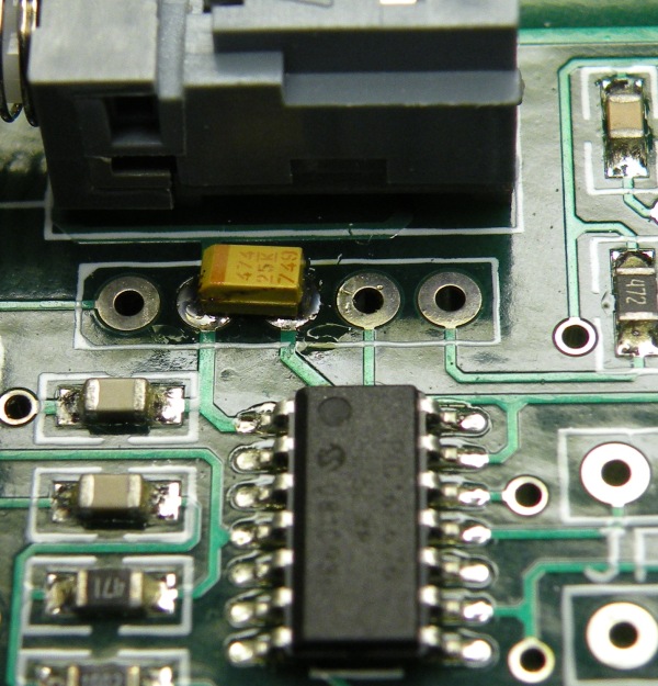
This prompted me to contact Tigertronics support, and this again evolved into a lengthy exchange of information and opinions --- suffice it to report that they finally admitted to a manufacturing error (a 33uF cap accidentally replaced by a 4.7uF), but at the same time maintaining that it has no real impact on the product's real-world performance! and offered to either modify the unit at the factory or send me the replacement capacitor if I wanted to undertake the repair myself, I took the part offer to avoid sending the unit half way around the World.
If the Cap at the red arrow is marked 4.7uF, it's (in my opinion, but unnecessary according to Tigertronics) a good idea to replace it with a 33uF/10V Tantalum capacitor):
You'll then see a significant improvement of the noise floor:
Much worse was their treatment of my frequency response "problem", they continue to claim a) That it's not a problem, and b) that it's due to a poor impedance match between the FT-847's data port and the SignaLink USB (why they have neglected to address that in the product design they refrain from mentioning, but I can report that the same symptoms exist when connected to the ICOM IC-756ProIII's ACC1 port).
They also refrain from publishing the optimum connection impedance or specifying their input impedance and frequency response.
There is something to be said in support of the poor match argument: When connected to the much lower impedance of the "Phone jack" the symptom is much reduced. It turns out that they have placed a 10nF capacitor across the primary winding of the isolation transformer, apparently in an attempt to attenuate the higher end of the AF-spectrum somewhat. They (Tigertronics) claim it's there to guard against RF entering the circuits. When removing this, the symptom got worse!
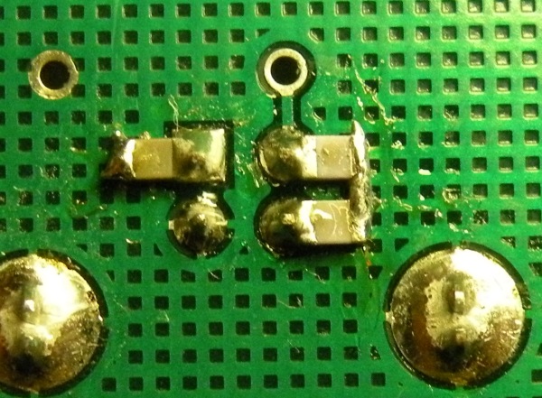
This is the original transformer used by Tigertronics (after removal)!
Since Tigertronics flatly refused to let me have the schematics of the product for a more in-depth analysis (quoting protection of trade secrets!), I saw this as my most likely point of modification, and replaced the original transformers with proven (I've used them in all my home brew interface projects) 600/600Ohm audio transformers (salvaged from analog telephone switch equipment) and of cause left the 10nF capacitors out:
I've later (not in picture) mounted 1nF ceramic capacitors where the 10nF used to be, and cannot see any measurable difference with or without these, so I've left them in.
These transformers are a poor mechanical fit, but were exactly what the modification required. I now have this frequency response (again FT-847, 144MHz white noise from Data port):
I found a couple of other transformers (also ex-telephone equipment) that were a better mechanical fit
There are lots of similar 600/600 Ohm audio transformers available from commercial sources (Radio Shack; Farnell etc.), if you can't find some in old analog telephone equipment (modems, telephone, switches etc.).
And they produce equally good results (despite having Ferrite cores!) as seen here:
I've done some further experimentation with decoupling of the USB signals from the computer:
Each of the USB interface pins have gotten 1nF caps to Ground.
Colin, G8TMV writes:"I must disagree with one of the mods, adding 1nF caps across the
USB data lines is a very *bad* idea, it will distort the USB data
signals very badly. You should use 10pF at most."
I'll try that and get back here with any necessary updates.
Update 18.08.2014:
I've done the 10pF mod, with no change seen at all - good or bad, so the 10pF value is recommended for this mod.
Update 10.09.2015:
I now recommend removal of this mod, if you have performed it. As pointed out, it brings the USB connection out of specs, and make no detectable difference to the noise measured. It actually disables USB connection with certain combinations of fast ports and cables.
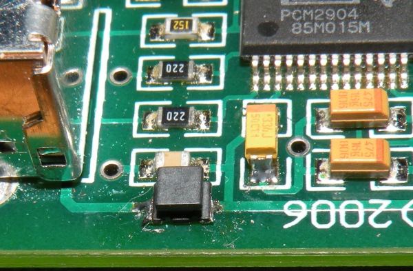
The power supply (from USB) has been cut, and a 100nH choke inserted,
and a 4.7uF capacitor added at the PIC supply line (the picture erronously shows a 0.47uF cap - it was corrected after the picture was taken).
The end result of these additional modifications is a small but measurable improvement of the noisefloor (a few dB):
and finally the product meets my expectations!
Why Tigertronics haven't done this, is beyond my understanding, all it takes is five extra passive SMD-components, changed values of a couple more and two different (but probably equal priced) isolation transformers. Their claim that "it doesn't matter", has substance only if all you use the SignaLink USB for, is running stuff like RTTY, SSTV and partially PSK31 on noisy HF-bands and make sure to keep wanted signals away from the low end of the pass-band. If, on the other hand, you're chasing very weak signals on the higher HF-bands and VHF/UHF, looking for "invisible/inaudible" signals in PSK31, JTxx, WSPR and FSK441, oftentimes 28-33dB below the noise, you need all the headroom and linearity you can get, and the SignaLink USB as shipped simply doesn't cut it! As shipped the product is suitable only for connecting to the low impedance speaker/headphone output, not the more suitable fix-level, but higher impedance Line connector. It's a pity since only these few changes, brings it to excel, proving that the basic design is OK, just lacking the engineering polish.
PS: Tigertronics has made a mistake in their instructions for connecting the Signalink USB to the ICOM IC-756 PROxx Microphone/Headphone/Loudspeaker I/O (and presumeably other radios which supply the microphone with DC through the Mike-pin) in omitting to specify that a blocking capacitor (100 nF will do nicely) need to be inserted between mike input and the isolation transformer (it would do no harm as a standard part of the circuit). If the DC is let through, the transformer core is saturated (gets very warm), and the signal gets severely distorted or even blocked.
Having a problem with distortion of audio from my Orion II Line-Out, I discovered that this output had a DC component of 5V (for no apparent reason). I have now adopted the policy of using a DC-blocking capacitor on both input and output, and at the same time started using a DIL-16 solder block for the option wiring instead of the yellow wires, this gives a much better contact than the too thin wires do.
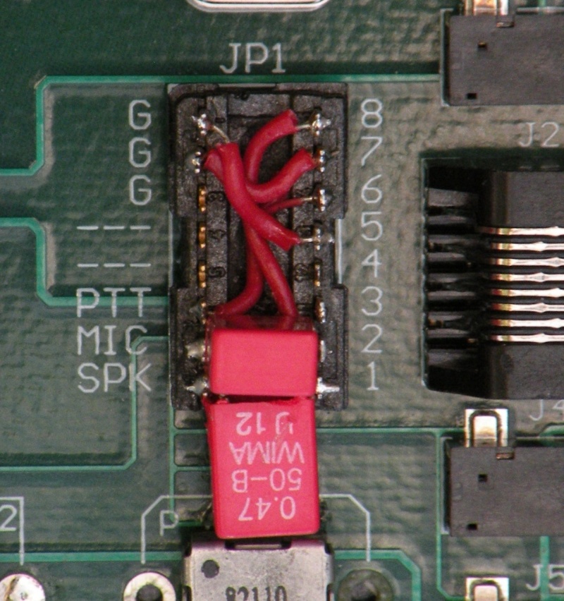
Universal Option Plug for the Yaesu FT-847 and the Ten-Tec Orion, I made this common and adapted the cables, so that I can swap cables only when switching radio.
This "universal" option Block is wired thus:
SLUSB Side RJ45 Side
G -------- 5
G -------- 7
PTT ------ 6
MIC -470n- 8
SPK -470n- 1The TenTec Orion AUX-Cable:
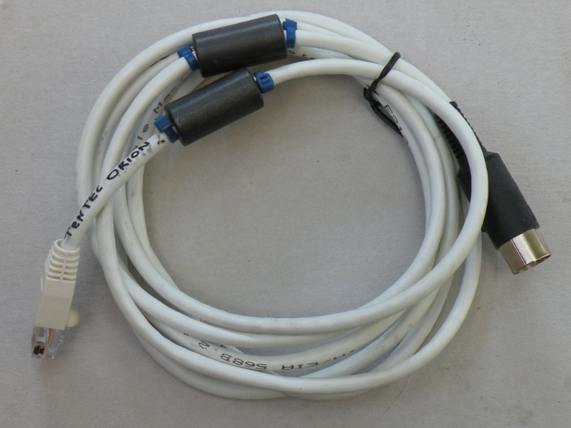
Is wired like this:
SignaLinkUSB --- TT Orion Cable
RJ45 8-pin DIN
1 ------- 1 (Line In)
7 ------- 2 (GND)
6 ------- 3 (PTT)
8 ------- 4 (Line Out)
And the Yaesu FT-847 Data-Cable:
The small piece of perf-board hiding within the red shrink tubing connects the two cables securely and inserts the 1K8 resistor in the circuit.
The cable wiring is:
SignaLinkUSB --- Yaesu FT-847 Cable
RJ45 3.5mm StereoJack
1 ------- RING (Line In)
7 ------- RTN (GND)
6 --1K8-- TIP (PTT)
8 ------- TIP (Line Out)
SignaLinkUSB --- Icom IC-756 PRO Family cable
RJ45 8-pin DIN
    1 ------- 1 (AF / Line Out)

    5 ------- 2 (GND)
7 ------- 2 (GND)
6 ------- 3 (PTT)
8 ------- 4 (MOD / Line In)
Cables for other radios can easily be made following this pattern.
PPS: Prompted by a couple of emails to me, spurred by the publication of this page, I've made a couple of measurements of SignaLink USB output. The output was fed into a SoundBlaster16 Line-input and mapped by SpectraLab as usual.
Driven by WSJT7 in JT6M mode, I get the following: First in Rx mode (noisefloor or idle noise):
And then Tx'ing:
These shots were made with my Mod'ed SignaLink USB, and I see nothing wrong with the results.
PPPS: It has been suggested to me, that my unit could somehow have left the manufacturer defective, and thus that this state of affairs would be a non-recurring fluke - as I have examined and modified 6 different units (four of them the bought at roughly the same time, from the same dealer, and two imported from different sources in the US) and found all of them essentially identical in their behaviour I find this highly unlikely - and BTW: all of them had the 4.7uF cap (claimed to be a manufacturing error), not the 33uF, installed!
ADDENDUM 5.01.2009: I have been told by one source, that units sold now, are equipped with the 33uF capacitor and better (flat) audio transformers, if this is indeed correct I can only be happy! Maybe my criticism helped Tigertronics decide to correct the problems instead of just trying to deny their existense :-)
PS: As of 05.04.2009 I have examined three newly acquired units, and sadly this is apparently not true, they do have the 33uF cap but the same sh**** transformers. As units have no serial numbers or production date I cannot be absolutely certain about this.
Orin, KJ7HQ writes about his fight with noise generated by his laptop, I quote:
Peter,
Your site has been an inspiration.
I just got a Signalink USB and it did have the 33uF cap. But noisy on both receive and transmit. It also had a defective cable to start with, but it was easy enough to crimp on a new RJ45.
I looked at what that 33uF cap seemed to be for and it's just to smooth the voltage reference (or virtual ground) for the op-amps. Unfortunately, ground for the signals to and from the sound chip is the same as the USB 5V ground so any noise on the virtual ground gets added into the tx and rx signals. Looking further, the 33uF is just on the lower leg of a voltage divider, two 1k resistors so what we effectively have is a low pass filter on the power supply. My USB 5V power was horrible - the result was noise in the receive spectrum (and no doubt transmitted too) as bad as -50 dB below 100Hz.
So I replaced the upper 1k resistor with a 3V low dropout voltage regulator, with its input going to the 5V supply, ground to a convenient ground via and output through a 200 ohm resistor to the 33uF cap. This gives a 2.5V reference/virtual ground as did the original voltage divider with much better decoupling from the USB 5V power supply. This has given me a 30dB improvement below 100Hz as shown by the RX spectrum in MixW - noise is now -80db or better in this range and close to -100dB elsewhere.

No doubt I'll get further improvements putting a choke in the power supply as you did - I had spare 3V regulators around, but not chokes.
I have another problem with my signalink. It oscillates at about 3.8 MHz when the TX control is between 9 and 3 o'clock! I've not yet worked out why this happens... it happened both before and after my mod.
Orin.
ADDENDUM 21.08.2012: Mat, AB8VJ, has come up with another way of reducing the noise coming from the USB power-line. He's using the 3.7V reference from the PIC to BIAS the op-amps instead through a modified Voltage divider (470/1000 Ohm instead of 1K/1K), I've modified my unit this way, and it works wonders:
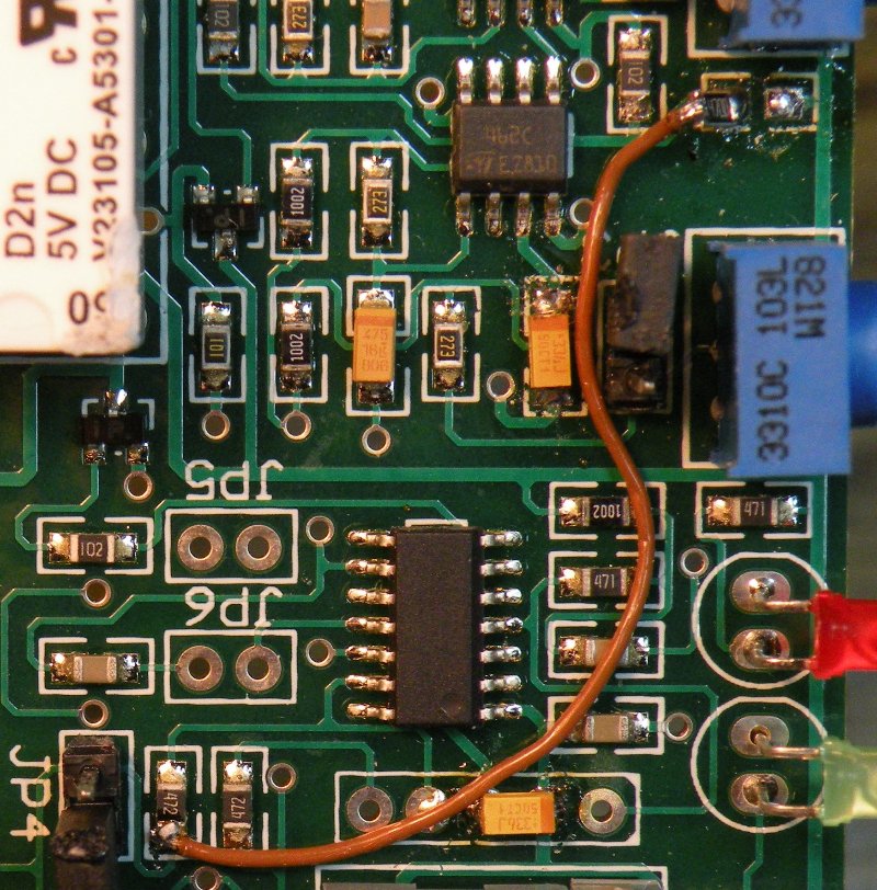
All it really is is the brown jumper wire, taking the 3.7V from the reference source, to a 470 Ohm resistor on it's end , replacing the upper 1K Ohm resistor connecting the voltage divider to the 5V rail.
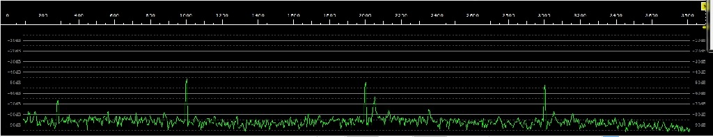
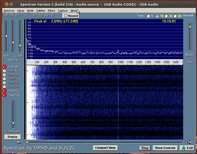
The result is very pronounced:
First my unit before the mod:
And then after the mod:
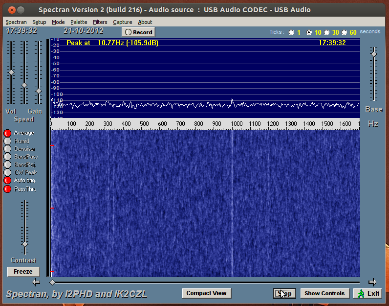
Now I just need to get rid of that pesky 1KHz birdie!
I Have obtained Mat's permission to include his final draft of the article: Rettysnitch Corner: When good enough just isn’t ***Updated!***
Mat has also reverse engineered the schematics. ***Updated! - Again 06.11.2013***
I QSP from Eric / WV3E: How to Read the Date Code of a SignaLink USB
......I got this procedure when corresponding with SignaLink a while back, thought you might find it useful:
1. Turn the SignaLink OFF.
2. Using metal tweezers (or something conductive), short the two pads that are labeled "JP5" (they are right above the JP5 label).
3. While shorting the above pads, turn the SignaLink ON.
4. When the green power LED goes out, you can remove the short and then immediately start counting the number of blinks.
5. The LED will blink the month and the year (there will be a slight pause in between).
The recent reports (July 2015) of driver errors for the TI PCM290x (AKA USB Audio CODEC) series of sound devices (Used in the SLUSB amongst many others). does apparently affect Win7x, Win8x and, possibly, Win10, only. OS-X (Apple Mac) and all versions of Linux are unaffected by this specific Win driver problem, as is indeed good old WinXP.
A thorough explanation of the problem and how to circumvent it can be found here:
https://www.youtube.com/watch?v=guH0NMRRTAo&feature=youtu.be